Beranda
/ Timer And Contactor R Relay Diagram / How to wire forward reverse motor control | 3 Phase motor ... / Each relay activation will cause the light to toggle.
Timer And Contactor R Relay Diagram / How to wire forward reverse motor control | 3 Phase motor ... / Each relay activation will cause the light to toggle.
Insurance Gas/Electricity Loans Mortgage Attorney Lawyer Donate Conference Call Degree Credit Treatment Software Classes Recovery Trading Rehab Hosting Transfer Cord Blood Claim compensation mesothelioma mesothelioma attorney Houston car accident lawyer moreno valley can you sue a doctor for wrong diagnosis doctorate in security top online doctoral programs in business educational leadership doctoral programs online car accident doctor atlanta car accident doctor atlanta accident attorney rancho Cucamonga truck accident attorney san Antonio ONLINE BUSINESS DEGREE PROGRAMS ACCREDITED online accredited psychology degree masters degree in human resources online public administration masters degree online bitcoin merchant account bitcoin merchant services compare car insurance auto insurance troy mi seo explanation digital marketing degree floridaseo company fitness showrooms stamfordct how to work more efficiently seowordpress tips meaning of seo what is an seo what does an seo do what seo stands for best seotips google seo advice seo steps, The secure cloud-based platform for smart service delivery. Safelink is used by legal, professional and financial services to protect sensitive information, accelerate business processes and increase productivity. Use Safelink to collaborate securely with clients, colleagues and external parties. Safelink has a menu of workspace types with advanced features for dispute resolution, running deals and customised client portal creation. All data is encrypted (at rest and in transit and you retain your own encryption keys. Our titan security framework ensures your data is secure and you even have the option to choose your own data location from Channel Islands, London (UK), Dublin (EU), Australia.
Timer And Contactor R Relay Diagram / How to wire forward reverse motor control | 3 Phase motor ... / Each relay activation will cause the light to toggle.. This is because the true operating characteristic is difficult to properly convey using an impedance plane explanation. Am i just connect the no of the timer series to motor start button, and 3 phase motor contactor/overload relay starter Two types of timer we use in rlc circuit, electronic timer and mechanical timer. A 12v relay is used to drive the ac load connected at the output.
Truly, we also have been remarked that photocell and timeclock wiring diagram is being just about the most popular field right now. 3 pole contactor without base contact 4 pole contactor with 4 n.o. At the same time, relays are able to control electrical and electronic circuits of many different characteristics by switching without being affected by different frequencies and wave types. It shows the components of the circuit as simplified shapes, and also the power as well as signal connections in between the gadgets. That is why i would prefer to use a separate 20 amp 120 volt circuit for control voltage, no fuse required.
Packard C230b Wiring Diagram | Free Wiring Diagram from ricardolevinsmorales.com 3 pole contactor without base contact 4 pole contactor with 4 n.o. Using an adapter plate, you can also mount it for standalone use. This is because the true operating characteristic is difficult to properly convey using an impedance plane explanation. The basic element of a ladder diagram is a contact. Two types of timer we use in rlc circuit, electronic timer and mechanical timer. The timer is just a switch to control the relay (contactor), just run power through the timer on the way to the coil on the contactor. 4 pole control relay with 4 n.o. Contactor wiring guide for 3 phase motor with circuit breaker.
We attempt to talk about this contactor wiring diagram with timer pdf image here just because based on info coming from google search engine, it is one of many top searches key word on
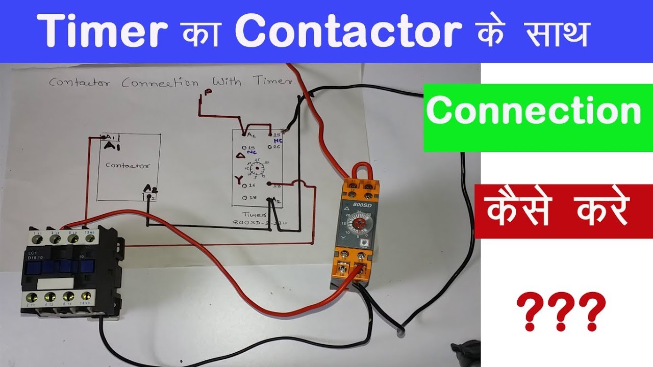
A contact has o nly two states: With help of following timing diagram we can easily understand working of timer. Switching two relays at one time is like flipping 2 switches at once….with the same result. F delay timer wiring diagram best qd 253 post purge timer f. Time delay relays are simply control relays with a time delay built in. Using an adapter plate, you can also mount it for standalone use. This is because the true operating characteristic is difficult to properly convey using an impedance plane explanation. Contactor wiring guide for 3 phase motor with circuit breaker. In this video, we discuss how to a delay timer connect with contactor and how a delay timer work as an on delay and off delay also discuss wiring diagram and. The circuit that applies the voltage to the coil is referred to as the control circuit , because it controls the main device that the contactor or relay is switching. F delay timer wiring diagram best qd 253 post purge timer f. Use these tips to learn how to wire a contactor. 240 volts ac and 480 volts ac are commonly used for these large pieces of.
Power poles 3 pole reversing contactor set. The relays which are used after the manufacture of thyristors and triacs based on the semiconductor principle are still used in applications requiring very. I have the contactor and timer sketch below, hope its clear enough. With help of following timing diagram we can easily understand working of timer. Each relay activation will cause the light to toggle.
Contactor Wiring Diagram with Timer Unique 11 Pin Relay ... from i.pinimg.com A contact has o nly two states: A 12v relay is used to drive the ac load connected at the output. Each relay activation will cause the light to toggle. These diagrams are meant to be conceptual but often we try to take them literally. When the time has expired, the contacts close — and remain closed until voltage is removed from the coil. F delay timer wiring diagram best qd 253 post purge timer f. Timer has two element, timer and relay. This sample is particularly useful since you can replace one relay (as shown in the diagram) with a physical light switch.
Am i just connect the no of the timer series to motor start button, and
Hence time t=120k*470uf=6 2 seconds~1 minute (approximately). Time delay relays are simply control relays with a time delay built in. F delay timer wiring diagram best qd 253 post purge timer f. A wiring diagram is a streamlined traditional photographic representation of an electrical circuit. The relay logic control works efficiently to perform basic on/off operations by opening or closing the relay contacts but it involves a humongous wiring. 240 volts ac and 480 volts ac are commonly used for these large pieces of. Truly, we also have been remarked that photocell and timeclock wiring diagram is being just about the most popular field right now. Timer has two element, timer and relay. Using an adapter plate, you can also mount it for standalone use. The relays which are used after the manufacture of thyristors and triacs based on the semiconductor principle are still used in applications requiring very. These diagrams are meant to be conceptual but often we try to take them literally. It shows the components of the circuit as simplified shapes, and also the power as well as signal connections in between the gadgets. Contactor wiring guide for 3 phase motor with circuit breaker.
A contact has o nly two states: Each relay activation will cause the light to toggle. The circuit incorporates relays along with other components such as switches, motors, timers, actuators, contactors etc. 3 phase motor contactor/overload relay starter Eaton wiring manual 0611 5 2 contactors and relays 5 5 contactor relays contactor relays contactor relays are often used in control and regulating functions.
DIAGRAM Electrical Contactor Diagram FULL Version HD ... from i.ytimg.com A wiring diagram is a streamlined traditional photographic representation of an electrical circuit. I have the contactor and timer sketch below, hope its clear enough. Each relay activation will cause the light to toggle. An open contact holds the current flow whereas a closed contact permits current to flow through it to the next element. Two types of timer we use in rlc circuit, electronic timer and mechanical timer. Using an adapter plate, you can also mount it for standalone use. Truly, we also have been remarked that photocell and timeclock wiring diagram is being just about the most popular field right now. Other types of commonly used relays include the time delay relays, protection relays, solid state relays and reed relays.
Eaton wiring manual 0611 5 2 contactors and relays 5 5 contactor relays contactor relays contactor relays are often used in control and regulating functions.
Each relay activation will cause the light to toggle. That is why i would prefer to use a separate 20 amp 120 volt circuit for control voltage, no fuse required. Generally, control relays are intended for controlling relatively low current applications, more or less in the range of 300 va to 2000 va. When designing circuits using time delay relays, questions such as what initiates a time delay relay, does the timing start with the application or release of voltage, when is the output relay energized, etc., must be asked. Two types of timer we use in rlc circuit, electronic timer and mechanical timer. Assortment of timer relay wiring diagram. A contact has o nly two states: A wiring diagram is a streamlined traditional photographic representation of an electrical circuit. In this video, we discuss how to a delay timer connect with contactor and how a delay timer work as an on delay and off delay also discuss wiring diagram and. Other types of commonly used relays include the time delay relays, protection relays, solid state relays and reed relays. Relay logic basically consists of relays wired up in a particular fashion to perform the desired switching operations. F delay timer wiring diagram best qd 253 post purge timer f. Power poles 3 pole reversing contactor set.